June 6, 2004: 4th Cable Stay (west platform),
East side platform extension (resting on the west pylon) and
West tendon termination. Note the platform with the blue wheel - for
preparing cables to be pulled up the stay pipe.
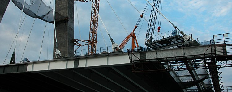
East side platform extension of the west pylon platform
(July 11, 2004 note: There are no obvious counterweights because of the near
symmetry (4 anchor extension segments in each direction)
in westward-directed platform weight and the eastward-directed
platform weight even though the cross beams for the eastward-directed segment
were not yet placed.
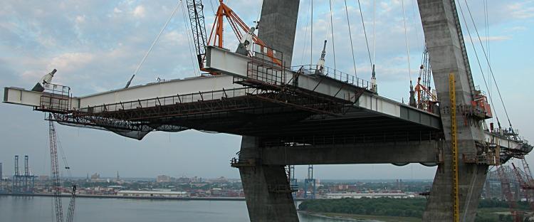
Two stacks of concrete blocks, acting as counterweights are quite obvious on
the July 04, 2004 photos when the eastward- (5 anchor extension
segments) and westward-directed (6 anchor extension segments)
platforms were asymmetric in length
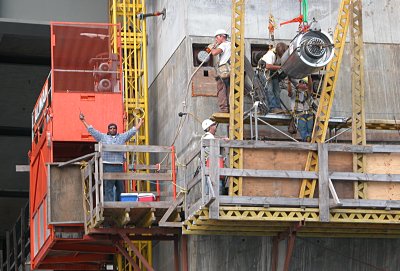
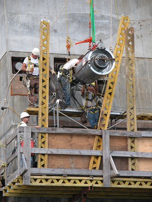
Tendon termination and stressing (west pylon)
|
On the left is our team: Rocky (left, emerging from the orange
elevator), man-on-break (top middle),
two workers (top right) and of course the supervisor, supervising
(lower middle). The two workers appear to be threading the individual
cables into the termination assembly.
|
On the right is a detailed view of the
cable termination housing. Note the individual cables extending out of
the end of the termination housing (about 40 individual cables each
about 15 mm diameter).
|
Boyd Gregg has contributed the following insights about the cable and
tensioning process:
"With regards to the ports at the bottom of the photo, these are actually
post tensioning cables (actually referred to as tendons). These tendons do
exactly what you suggested. They are tensioned to the proper force with the
large hydraulic ram you have pictured on your website and I have included
below. This ram is only used temporarily and after the proper force is
applied a wedge is used to hold that tension in the tendons permanently. I
was unable to find a good picture of the actual wedge and tendon
arrangement. That tension holds the legs of the tower together and keeps
them from "kicking out". As you can imagine, with thousands of tons of
concrete and road deck on top of these legs they would tend to spread apart."

This work is licensed under a Creative Commons License.
Attribution: C. Frank Starmer from http://ravenelbridge.net
_