When I arrived at the Aquarium about 7am, the
light was not so good. I took my photos and thought - hmmmmm, there
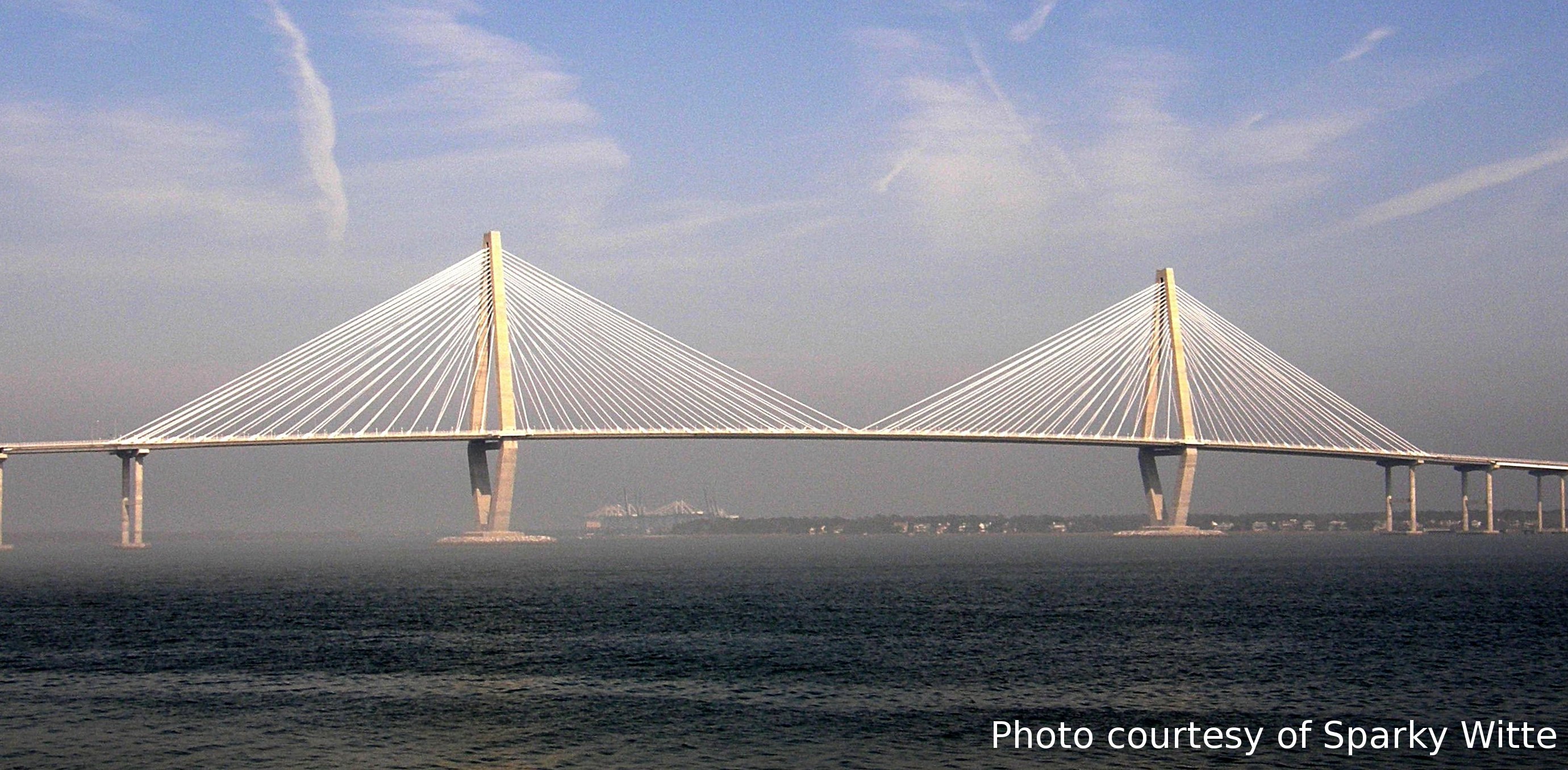
is probably little traffic on the Pearman Bridge (which parallels the new
bridge construction site). I thought that perhaps it might
be possible to ride my bicycle along the edge of the construction site,
shoot a few
photos from various point along the Pearman Bridge and specifically
concentrate on the hurricane support anchors
(Ellen and I are having some discussion of
the anchors). More important, with little traffic on the Pearman, perhaps
I might even live to tell about it.
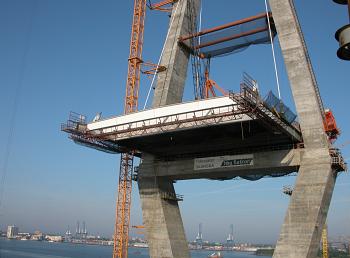
May 9, 2004 was the start of almost weekly bicycle rides across the Pearman,
taking photos of the approaches, the west and east main span sections and
then turning around and riding home.
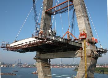
Returning again after next two weeks, I found that there is a lot of
observable detail about bridge construction that changes from week to week.
So this page of bridge construction details was the start of up close
and personal photos of the construction
as I rode across the old Pearman Bridge.


|
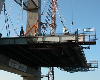
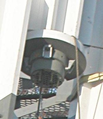
West Tower: Anchors on the West Side
|
West Tower: Anchors on the East Side
|
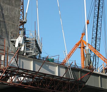
Stages of Anchor Attachment
|
Anchor Attachment: Master strand pulled
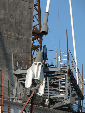
|
Anchor Attachment: completed
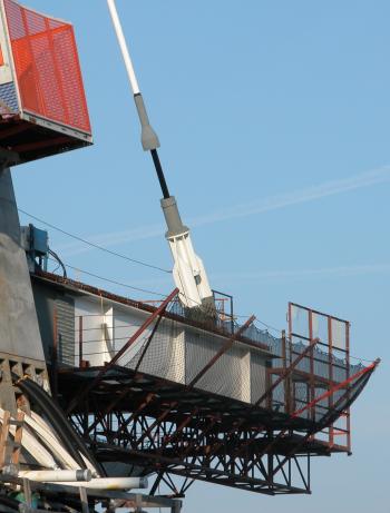
|
My speculation is that the early attachment (left) reflects a thin,
fish-tape for pulling the main cable (from either above or below ?)
while the right anchor reflects the final cable
in place. My question is - how is the tension between cable and bridge
initially created and then maintained? Are the cable from either side of the
support a single cable - or two cables with tension management done inside the
concrete supporting structure? July 21, 2004 - With an engineer from
SCDOT, I learned all about pulling these cables (see
all about cables. The polyethylene shield is
placed and there is indeed either a fish-tape analog or some other sort
of cable to get the pulling process started. Then cables are pulled from
the deck to the main pylon, two at a time, with 50% tension used to hold them
in place. After the process of pulling all 39 cables is complete, the
tension is increased to the full tension.
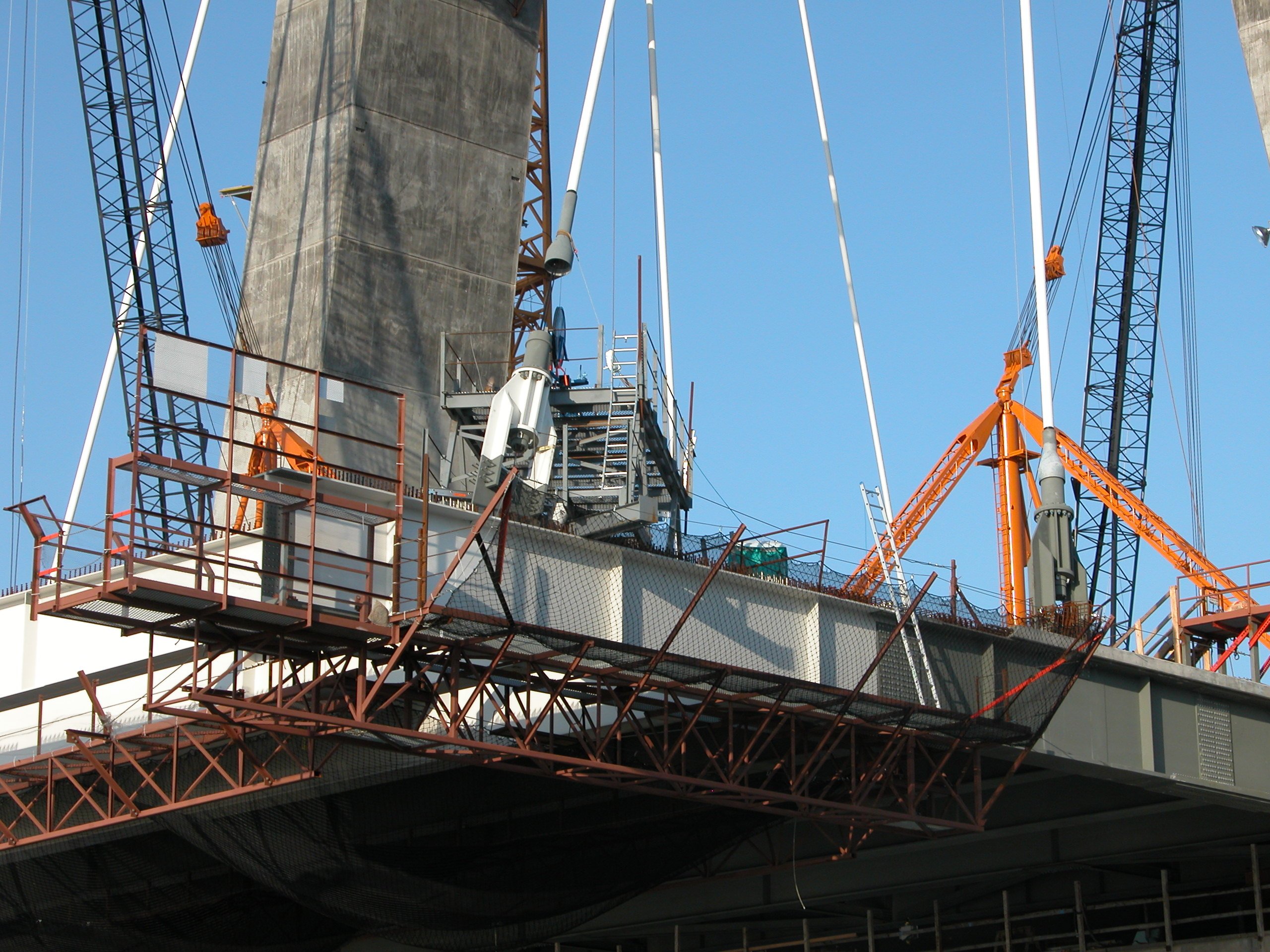
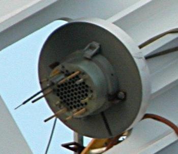
Note in the center of the left photo below
(click the photo) you can see portions of the cable jig.
The blue wheel with two grooves is for feeding the cable into the
white polyethylene shield. Three cables appear to have been pulled
and you can see their ends (scroll down to the bottom of the photo)
extending from the tension plate near where
the white anchor is attached to the beam. The other wire, I assume is the
fish-tape.
The termination plate extracted from the above photo and (to the right)
from the Oct 3, 2004 photo below shows the master strand tail that supports
the stay pipe.
Here are two schematics from
AAS-Jakobsen in Norway that describe the cable
anchorage in the pylons and on the roadway platform. Note that in the
Norway bridge, the platform cable anchorage penetrates the platform whereas
here, the anchorage is coupled to the upper part of the platform with a
(steel) plate with wings - more like a jet aircraft outline than a cable
anchor.
Cable Anchorage: Pylon
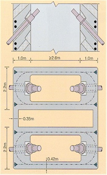
Cable Anchorage: Platform (This is not the strategy incorporated on
this bridge - but the schematic gives an idea of how the cable anchor
can be coupled to the platform. For the new Cooper River Bridge, the
anchors and attached to the side beams as shown in the two photos above.
The cables are passed through an anchor plate and then wedges are used
to transfer tension within the cable to the anchor plate.