July 21, 2004: Building the primary support cables
[July 3, 2005] Yesterday I watched the first stage of Le Tour
de France and remembered that a year ago I watched the French
cable-masters from Freyssinet construct a cable bundle. A lot
has happened in the past year and not only has SCDOT and Freyssinet
opened their doors for me, but PBC (and their parents, Tidewater Skanska and Flatiron) have gone out of their way to bring me into their
family. A big thanks to Wade, Peo, Marvin, Brian, David, Olivier and
Murray.
Bridge Photo RSS feed 
[July 21, 2004]
First - thanks to David Wertz, Jim Raines and Bobby Clair of SCDOT for
providing an opportunity to explore the engineering aspects of the bridge.
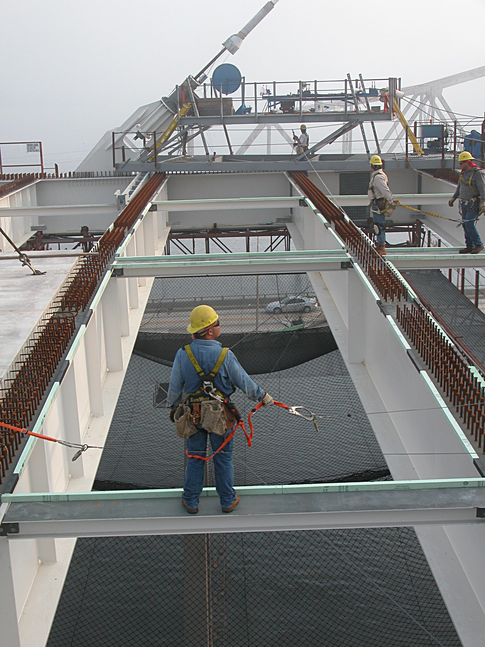
It was foggy when we arrived - watching the placement of a concrete
platform segment. A bit surreal, not knowing where I was going or what
I would see - just another trip through a foggy day (this day the
fog was real - not virtual). This left photo is through the wire mesh of
the elevator - just adding to the surreal nature of my adventure.


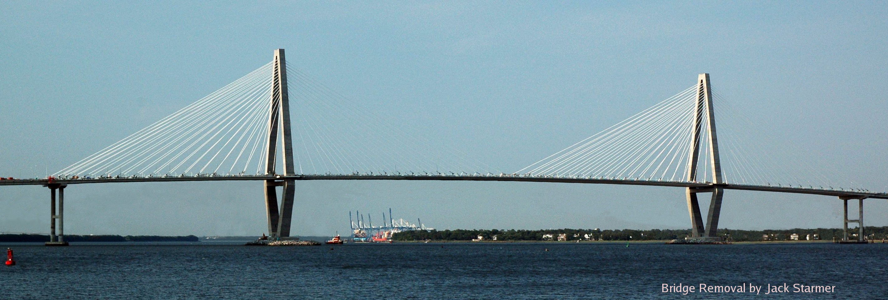
still foggy (left) but later, the weather was perfect (right)


From the top of the west tower (west, left; east, right)


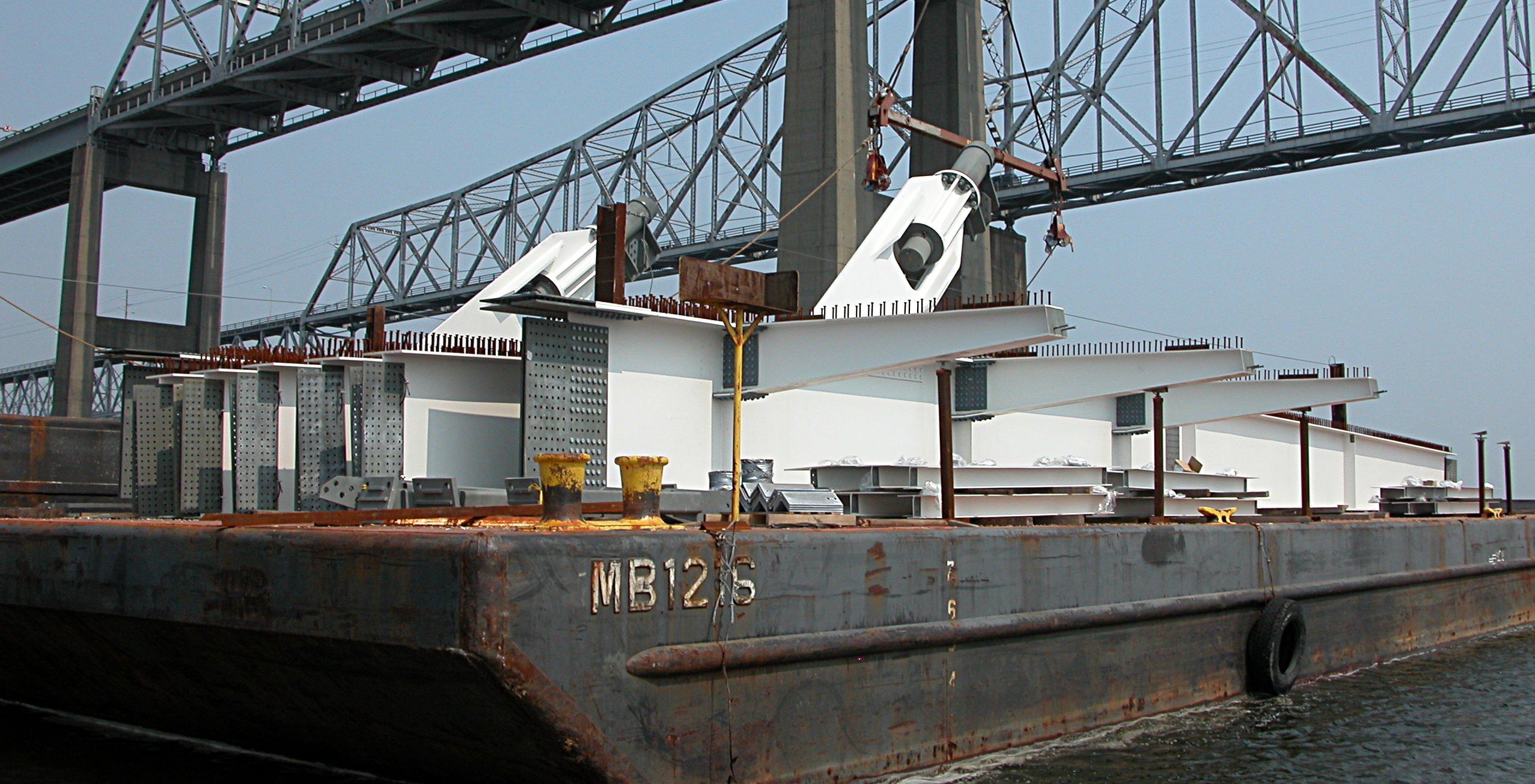
Anchorage beams waiting patiently on a barge. Note the perpendicular
short extensions on the right beam.
These support the bicycle and pedestrian path - which
can be seen on the right of the above photos of the east tower.
(Click on the above image
to convince yourself that there is indeed a bike
and pedestrian lane on the right side of the platform).

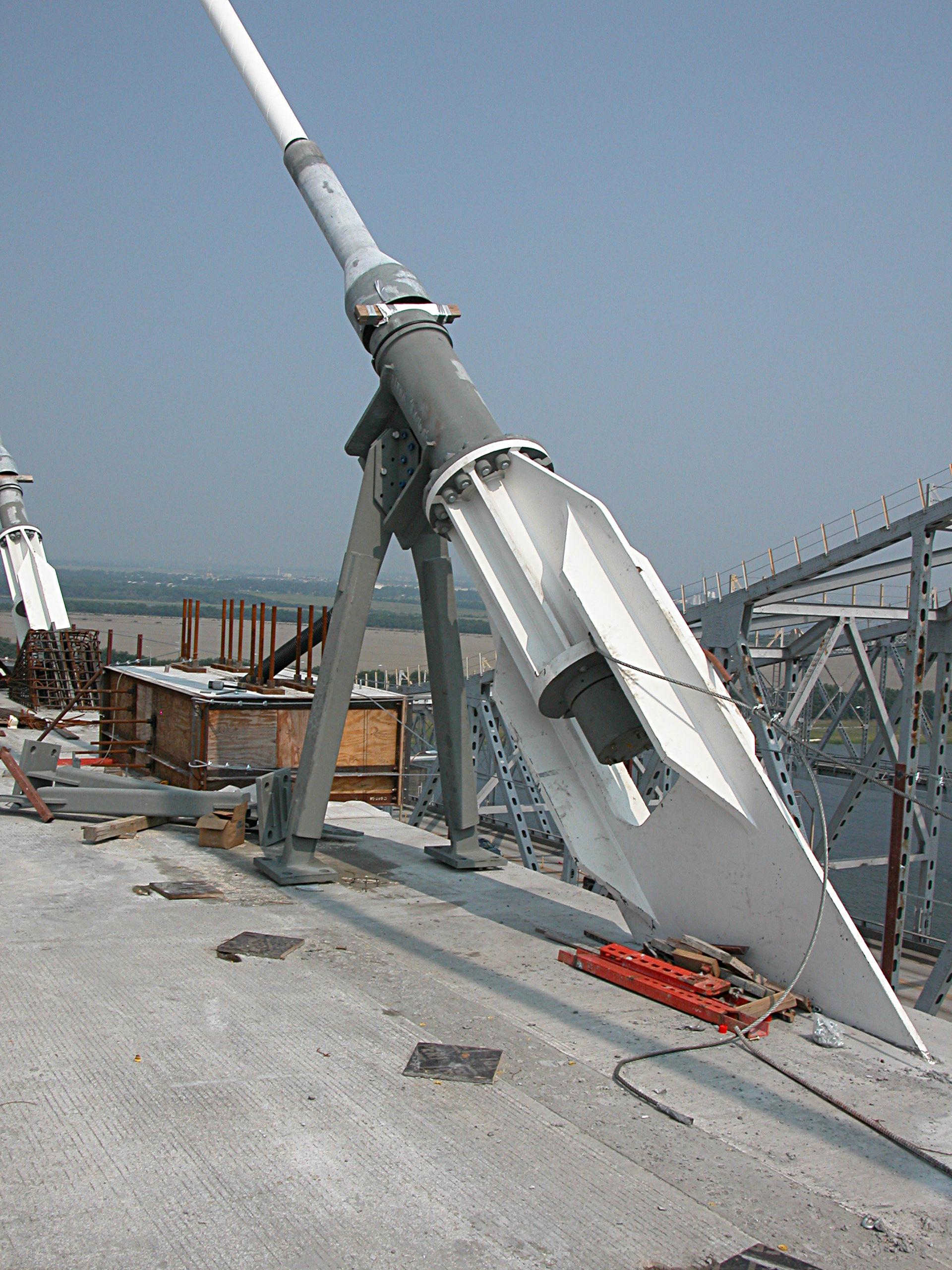
Two types of anchorage bases: reinforced concrete (left) and V brace (right)


The story of preparing the cable array - from start to finish
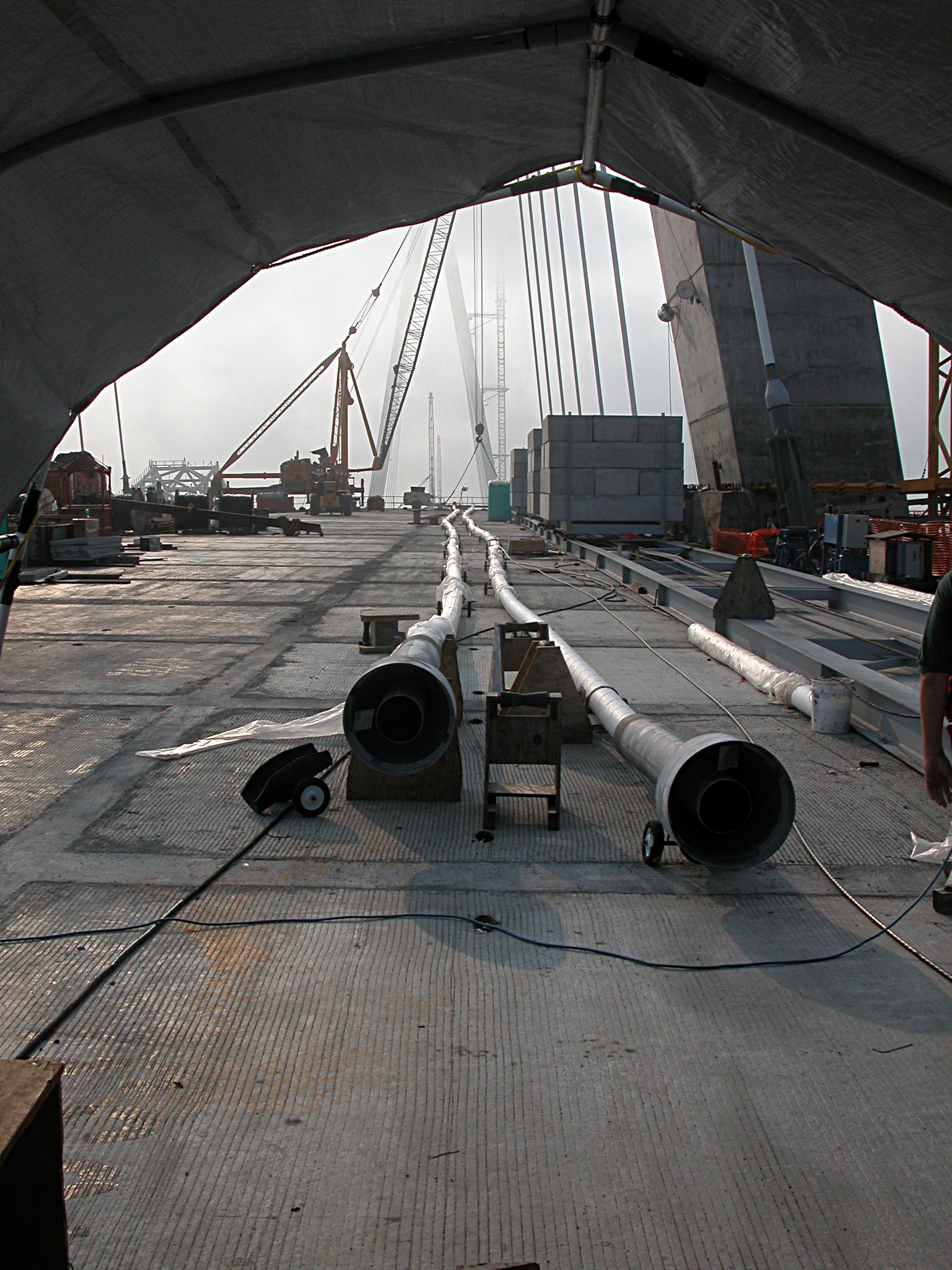
A view of the stay-cable pipes (left) and a cable assembly area
in the background


Its all in this small patented wedge -
This little 3 segment cone fits around the cable
with the smaller end pointed up for the platform end of the cable and
down for the tower end of the cable. As shown on the left - the wedge
fits into a wedge plate such that increasing tension results in greater
interface pressure between the wedge and the cable. This prevents the cable
from slipping. Anyone know a web site that describes the material properties
of these steel wedges? What is the force required for fracture, etc?


This is where it all starts - what I call the cable assembly platform.
Here you see the guys, the cable sheath, a blue wheel that guides the
cables from the cable spools (to the right, see below) into the sheath.
A more detailed display of post-tensioning of cables using the wedge
assembly is available at the
NIH Engineering Services (Unfortunately NIH has removed the construction
photos from their engineering web pages).
These give a detailed view of the cable, inserted wedge (left) and
haudralic pump (right).


Additional insights are gained from studying actual cables.
Post tensioning cables from the
Midbay bridge (pdf)
These guys do all the work of preparing the cable ends and feeding them
up the sheath.

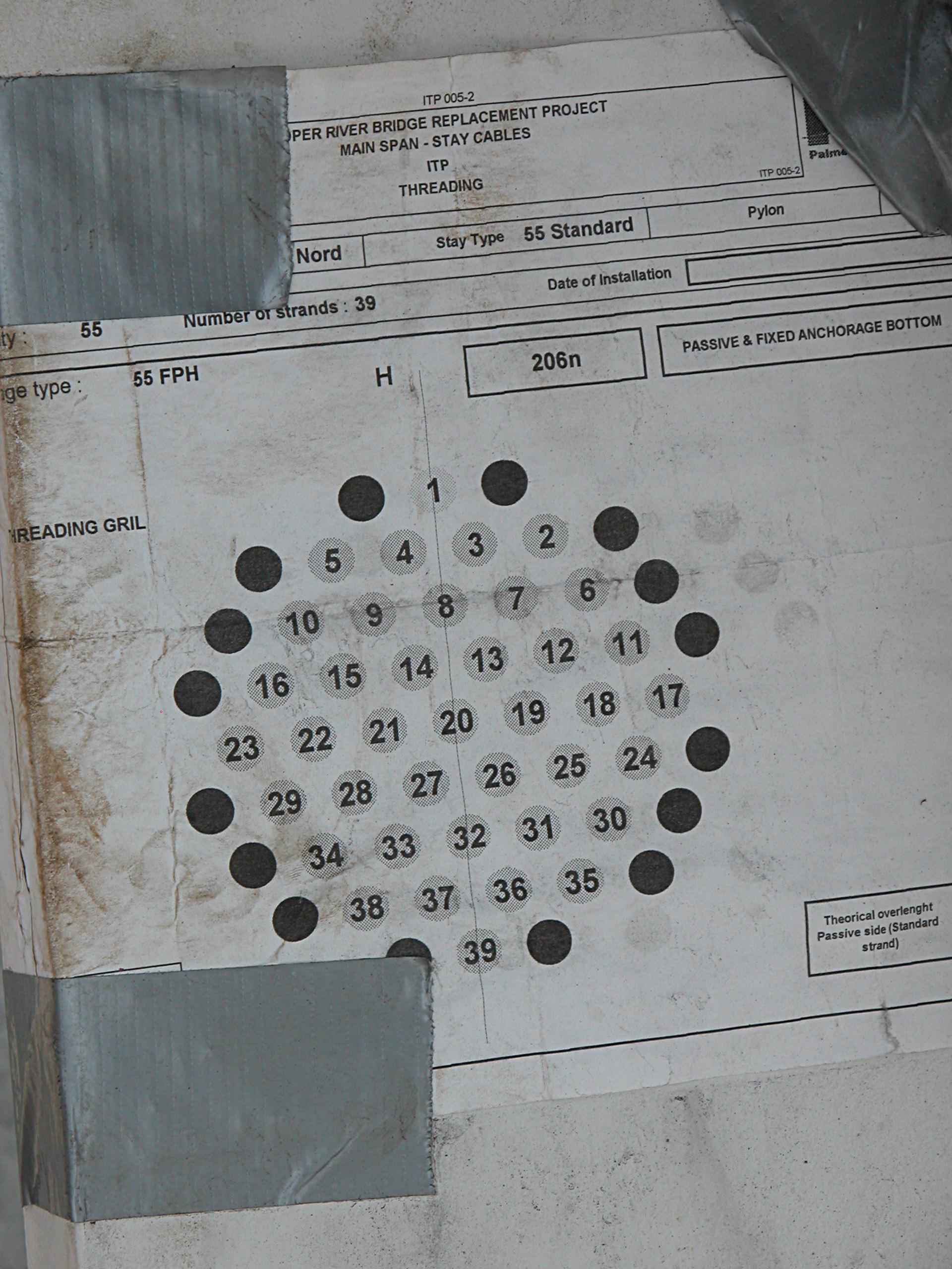
The sequence of cable insertion is
specified by the diagram on the left. Random insertion would lead to cable
crossins within the housing - but by following the sequence at each end,
the cables follow a parallel path from platform to tower.

On the left you see two cables with their ends trimmed ready to be
inserted into the cable housing (right) and pulled to the tower.


Cable being fed from spools

When the cable is secured at the tower end, it is then cut and prepared
for connection to the platform anchorage


Cutting the cable is the first step for preparing the cable ends
prior to insertion into the cable housing (below)


The prepared end is fed into the base of the cable housing: Cables
were being prepared for both the south (left) and north (right)
anchors.


Click for a quicktime video
showing
cable insertion into the anchorage. (This was rotated by quicktime on
a Mac OS-X and is the correct orientation. Played with Quicktime on Win?
it also has the correct orientation. Played with Win Media Player - you get
nice sound and no video)
Matthew has
also rotated it and
produced an AVI video but it seems to have problems with some viewers).
Waiting below the platform is
another worker, who will install the wedge and insert the cable into the
wedge plate. Meanwhile, additional cable
preparation continues on the outside of the tower. (I am not sure
what is happening here). Here is a view from the top of the west
tower (right). He appears to work for
Freyssinet, the French company
that is responsible for everything concerning the cables (providing all
materials and equipment, preparation and installation, stressing and all
the other zillion details required to properly install the cables).
Here is more information about
Freyssinet cable-stayed structures.
Here is one of the Freyssinet guys terminating a strand (left)
and Cyril, working in his nest near the top of the pylon


Since today is July 21, the Tour de France is almost over - and
what a surprise it is.
Perhaps from his vantage point, he is able to enjoy the Tour de France
and visualize the fantastic rides of his countrymen:

 Thomas Voeckler (left, riding for BRIOCHES LA BOULANGERE) who
held the yellow jersey for 10 days (starting with his unbelievable
ride during the stage 5 break away moving from 59th to 1st)
and Richard Virenque (right, riding for QUICK STEP)
who is king of the mountain once again.
(July 3, 2005: In the 2nd stage, Voeckler took the first king-of-the-mountain
jersey with a surprise attack near the end of the 2nd stage.)
Thomas Voeckler (left, riding for BRIOCHES LA BOULANGERE) who
held the yellow jersey for 10 days (starting with his unbelievable
ride during the stage 5 break away moving from 59th to 1st)
and Richard Virenque (right, riding for QUICK STEP)
who is king of the mountain once again.
(July 3, 2005: In the 2nd stage, Voeckler took the first king-of-the-mountain
jersey with a surprise attack near the end of the 2nd stage.)

Then there is rain. When rain falls on the cable sheaths, it will roll
over the sides, collect on the bottom and when there is enough mass to overcome
surface tension, a drop will fall. I see this as sort of like plucking
a violin string and with enough rain and enough synchrony of plucking,
harmonic motion may be induced into the cable. The spiral groove seen on
the right, as I understand it, is to disrupt the synchrony of departing
rain drops and reduce the likelihood of induced harmonic motion.
For more insights,
read about vibrations in bridge
cables or visit
Sympathetic vibratory physics:
It's a musical universe. To appreciate the reality of
resonance and vibration responses induced by external forces, here is a clip
of the wind-induced vibration of the
Tacoma Narrows Bridge (1940)


Inside there is another story. First, you have to get inside.
Here is a view of the elevator shaft inside the tower.

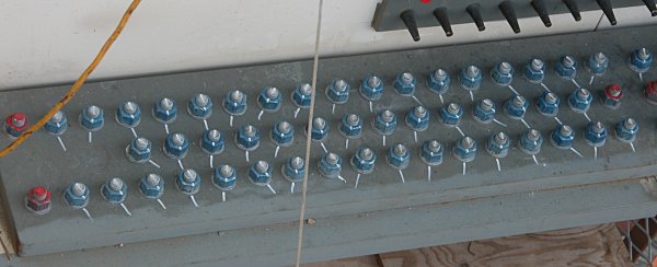
And here is an array of cable ends with wedges in place. Each cable passed
through the anchorage has a wedge placed on the strand to hold it in place.
In this photo, the cables have already received their final tensioning.
(East side).

On the west side, the cable array (39 cables) is being subjected to the
initial 20 - 30% of the final tension using hydaulic jack. A small conical
shaped steel wedge is slipped around the cable and pressed into the pressure
plate at the bottom of the array. The hydraulic jack then draws the cable
through the pressure plate about 3 inches / cycle.

Inside the tower, wedges are again attached to the cables and then
the proper tension (measured by the computer on the right) is produced
by a hydraulic jack (left).


Dropping the crossbeam in place between the anchorage extensions


Placing a cross beam - (before, left; after, right)


Splicing the anchorage extension (left) and bolting the crossbeam (right)


Attaching and splicing the beams is an interesting process. First
a drift pin is inserted in a few key holes to align the
beams.
Shown here is the initial bolt tightening (left) and applying the
final torque (right). Click the image for a quicktime video (15 Mb - be
patient).
Bolts are then inserted and torqued to a final value and then lines
painted on the top of each bold and on the beam to identify the position of
each bolt.
While the platform work is progressing, the approach piers continue to
grow. Here is shown the cap, joining the two columns to form a pier. A
second rebar cap will be placed on the right and then surrounded with
forms for creating the appropriate shape.

The pier before cap placement (left) and during (right)


and after placement

Finally, the lonely crane operator (left) and a ride down (right)


Our team on the way out (left) and on the way back (right)


And a friendly reminder - this is a no parking zone


This work is licensed under a Creative Commons License.
Attribution: C. Frank Starmer from http://ravenelbridge.net
_