An adventure with Freyssinet and their magic: design, materials,
installation and testing of stay cables.
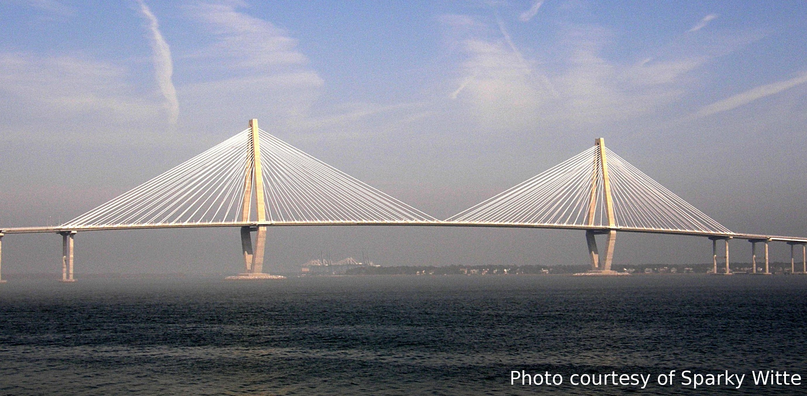
Each time I ride my bicycle across the old bridge,
I am attracted by the symmetry and geometry of the cables. Said another
way, my curiousity is ignited about the cable patterns, their anchors and the
engineering associated with their design.
As with High Steel Structures, the wonderful folks
(Oliver Forget and Eduardo Martins) at Freyssinet
offered me not only an inside look at the complexities of designing and erecting
a reliable cable, but lessons addressing some of the engineering
issues associated with the design of the cables and attachments.
Much information is also available in their magazine
Soil and Structures no. 220. Below I have
borrowed the figure illustrating the cable bundle and internal hydraulic
damper which controls cable bundle vibration.
So, my first curiosity was about the name "Freyssinet". Having finally
adapted to Internet-centric learning, I used
Wikipedia
and found that Eugene Freyssinet (from France of course) developed in 1928
the concept of pouring concrete around prestressed high tension steel cables
(tendons) in order to form concrete that had better tensile strength.
A short biography is available in
French or
English.
Apparently the
concept did not really develop in the US until the 50s. Post tensioning is the
process of developing tension after after concrete is poured over tubes that
contain tendons. The cables here, are post-tensioned by stages, to not only
support the bridge platform, but to create the geometric arc of the platform.
So, to hook up with the Freyssinet guys was like stepping into yesterday's
history with one foot and into tomorrow's designs with the other foot.
It all starts on the deck and here is one of their trucks (left) resting
peacefully under an array of cable pipes and (right) a look from the pylon
base illustrating what I consider the geometric beauty of a cable stay design.


Erecting the pipe starts at the top. First, the pipe is horizontal on the
deck surface. A master strand is initially cut to longer than its final
length. A marks are painted at each end, indicating
the correct length of the cable. The master strand is then passed through the
stay pipe. The array of stay pipe and master strand
is then lifted vertically by the crane to the stay work platform
on the outside face of the pylon. Here the stay pipe is secured and the
master strand is passed into the pylon interior.
These photos show this erection process.


Once attached at the top (left) the other end of the pipe is walked back
toward the anchor with a forklift.


Though out of sequence, this view of the top of the east pylon illustrates
the pipes and their preliminary attachment to the pylon. The left pipe
is 316 (north 16th cable) and the right pipe is 316 (south 16th cable).

So just what is going on with the guys on the outer face of the pylon?
Here you can see the stay pipe with the
master strand entering the interior of the pylon. He is pulling a secondary
line that eventually will be used to pull the cables introduced from the anchor
end of the stay pipe.

From inside the pylon, the master strand is slowly pulled gradually raising
the entire pipe as the length of the master strand is reduced.


Slowly slowly the fork lift walks the stay pipe closer to the
anchorage

Once the pipe reaches the anchorage area, the anchor end of the master
strand is passed down the anchor pipe and then through the tension plate
where it is locked into place with a small patented metal wedge.

Here the forklift support has been removed from the pipe and now the stay
pipe is supported totally by the master strand

Here the master strand tension is sufficient to align the pipe for
building the cable bundle.

and on Friday, here is the finished cable bundle

Sort of fun: looking down the cable housing and looking up the pipe


Here inside the pylon, near the top, the other end of the master
strand is being pulled by the isotension hydaulic system (patented) into the
pylon.

Eduardo tries to explain to me the tensioning process

The red mark indicates a position near the correct length for the master
strand

Later in the day, they erected the sister (316) pipe (initial tensioning)

Here comes Oliver for a conference

A very high level conference: Oliver, Brian and David (who wants to be
quoted as saying "We are building the best bridge in the world"). The
question for the day: How to
coordinate cable work with other work teams on the deck?

Cable pipes like everything else contract and expand with the temperature.
These pipes are made of polyethylene with a carbon fiber internal surface,
manufactured in France and shipped in 12 meter long pieces. These are
assembled on site and welded together. The longest pipe to the 316 anchor
is about 300 meters long. Here is shown the expansion coupling where a
sleeve overlays a section of the pipe. At the coldest temperatures,
there is at least 1 meter of overlap.

Last week I watched the installation of the last
shark fin edge girder.
Since last Friday, the floor girders have been installed and are ready for
placing the concrete floor panels.
Here is a view of the gap betwen the east and west decks as seen from the
top of the east pylon

David surveying the situation - jog or jump?

David taking a tethered jog across the gap

How do you get to the top? There are two elevators inside each pylon
serving the north and south cable anchors. To actually get to the top,
you ride the elevator to the top, walk up a ladder and emerge through
this door. What can you see from the top? You can
watch (10 Mb quicktime) the guys
working on the outside of the pylon and then scan the horizon. You can
also watch a Freyssinet guy
pull the guide cable up the pipe.

And of course, there are breathtaking views from the top looking east
and looking west (actually north and south also, I'll find those photos.


I could not resist trying to capture the dynamic growth of MUSC stretching
from US 17 to Calhoun St. Rutledge Tower is clearly seen on the left and if
you look in the middle, you will see Tom Basler waving from his office
in the white Library building.

More action on the deck. Here High Steel is delivering the last floor
girder

The girder was off loaded from the truck and (seen edge on).
The last floor girder is patiently waiting to be placed on the soon-to-be
erected missing piece, the center edge girder.

Of course, even when the weather is non-cooperative, sometimes there
are pleasant surprises and here is a colorful sunset against the
two pylons at the end of the day

However the day does not end when the sun says goodbye. Here is the big
boss - Oliver, working, as a demonstration to his team in France that he
actually works. How can you tell that he is working? Look at his right
arm and fingers, and the blur. This is very fast typing of email to the
team in France.